HD AEC | Acoustic Echo Cancellation SW
Removes unwanted echoes from audio signals without degrading the near-end voice quality

Acoustic Echo Cancellation Solution: High Definition, Full-Duplex, Multi-Mic Capable
True full-duplex acoustic echo cancellation under a wide dynamic range of audio levels. High Definition, Multi-Mic Capable, Full-Duplex AEC algorithm which includes noise reduction (NR), anti-howling, adaptive filtering, nonlinear processing, and double-talk detection.
HD AEC supports bandwidths from 8 kHz. (Narrowband-NB) to 48 kHz. (Full-Band-FB).
HD AEC is Adaptive Digital’s robust and proven Acoustic Echo Cancellation solution. The HD refers to high-definition digital signal processing that removes echo in full-duplex communication such as VoIP, video conferencing, and speakerphones by subtracting the loudspeaker signal from the microphone input, preventing the far end from hearing their own voice delayed.
Full‑duplex Acoustic Echo Cancellation refers to an AEC system that can cancel acoustic echo while both sides are speaking at the same time, without muting, clipping, or degrading either talker.
In other words, it enables true two‑way conversation in hands‑free VoIP systems.
Adaptive Digital Technologies’ high definition acoustic echo canceller (HD AEC), has integrated Noise Reduction and AGC into its AEC algorithm and created appropriate hooks to make them work together seamlessly.
Request Information
Acoustic Echo Canceler of the highest quality standards provides superior voice clarity to VoIP applications.
Customizable to your requirements.
Inquire with your specifications.
Fill out the form to receive more information
HD AEC Audio Demo - Listen
HD AEC Demo - Sampling Rate = 48 kHz

MICROPHONE INPUT (TX IN)
Female voice: ECHO – Male voice: Near End talker
Female voice (ECHO) is COMPLETELY REMOVED!
MICROPHONE OUTPUT (TX OUT)
Combining Acoustic Echo Cancellation with VQE algorithms to provide Superior Voice Clarity
Noise Reduction
- Introduced pre-NLP, resulting in a far cleaner audio stream
- Adapt to changes in the acoustic path (including gain/loss changes)
Auto Gain Control
- Boosts lower level speech signals in hands-free environments
Anti-Howling
- Identifies when instability is starting to occur and takes action to mitigate the instance of feedback loopingands-free environments
Platforms
HD AEC
Availability
| Platforms |
| Arm ® Devices – Armv7-A / Armv8-A / Armv9-A || Armv7-M / Armv8-M || Armv8.1-M || Arm® Devices – Armv7-M / Cortex-R5 || Legacy M3 |
| Texas Instruments – TI TMS320C7000 C7x | TI TMS320C6000 C64x/C64x+/C66x, C674x | TMS320C5000 C55x |
| MIPS Architecture – MIPS64 Preliminary |
| Analog Devices – SHARC |
| Operating Systems |
| Linux x86 (32-bit) / x64 (64-bit) |
| Windows 32-bit / 64-bit |
| Android |
| iOS |
Full Band Stereo HD AEC (SAEC)
Availability – Fullband Stereo HD AEC
| Platforms |
| Arm ® Devices – Armv7-M Cortex-M7 @ 48 kHz / Armv8-A / Armv9-A | Armv8-M Cortex M33/35, Armv8.1M Cortex-M85 |
| Intel Core i7 Mobile – 6600u – Skylake |
| Operating Systems |
| Linux x86 (32-bit) / x64 (64-bit) |
Features
- True full-duplex operation under a wide dynamic range of audio levels, even when microphone input signal is weak
- Programmable sampling rate, supporting narrowband (8 kHz), wideband (16 kHz), super-wideband (32 kHz), and full-band (44.1, 48 kHz)
- Improved adaptive nonlinear processor
- Handles echo tails of up to 500 msec. and greater, with true full-duplex cancellation.
- Spectrally representative comfort noise generator
- Automatically adjusts for unknown bulk (buffering/audio driver) delay
- Able to handle strong echo (speaker to microphone gains up to 20 dB)
- Anti-Howling
- Instantly adjusts to user-controlled speaker gain changes
- Handles external user-controlled volume changes
- Parameters are user configurable
- Improved fast convergence and reconvergence
- No divergence during double-talk
- Integrated Automatic Gain Control (AGC)
- Improves speech recognition performance in an echoic environment.
- Integrated Next Gen Noise Reduction (NR)
- Integrated Transmit Equalization
Overview
The acoustic echo cancellation software product provides superior voice clarity and true full-duplex performance under a wide set of challenging acoustic environments. It is capable of eliminating the acoustic echo in difficult conditions such as unbalanced speech levels, close speaker to mic proximity, indoor/outdoor environments, background noise, reflective room surface, double talk, and echo path changes.
Adaptive Digital’s HD AEC acoustic echo cancellation technology can be found in a wide range of applications, like IP Intercom Systems, Conference Speakerphones for both large and small conference rooms/huddle rooms, IP Desk Phones, Mobile Handsets, Radio over IP, and essentially anywhere where voice quality is affected by adverse room conditions. Additionally, the HD AEC acoustic echo canceller is effective in improving the performance of speech recognition algorithms when operating in an echoic environments.

Specification Tables
ARM Devices
HD AEC Armv8-A | A53 / A72
CPU UtilizationA53 Board: MCM-iMX8M-Mini, Cortex-A53, 1.8GHz
A72 Board: Raspberry Pi 4, Cortex-A72, 1.5 GHz
| Platform | Sampling Rate | Tail Length (msec) | Avg MIPS | Max MIPS |
| Cortex-A72 | 8 kHz | 256 | 14 | – |
| 16 kHz Wideband | 256 | 28 | – | |
| 48 kHz Fullband | 256 | 88 | – | |
| Cortex-A53 | 8 kHz | 256 | 24.5 | 50.5 |
| 16 kHz Wideband | 256 | 57 | 94 | |
| 48 kHz Fullband | 256 | 187 | – |
HD AEC Armv7-A Cortex-A8/A9/A15/A17 | Armv8-A | Armv9-A
CPU Utilization & Memory RequirementsAll Memory usage is given in units of byte.
| Platform | Sampling Rate | Tail Length (msec) | Min MIPS | Avg MIPS | Max MIPS | Per Channel Memory |
| Cortex-A8 | 8 kHz | 32 | 50 | 56 | 74 | 24k |
| 64 | 52 | 58 | 74 | 33k | ||
| 128 | 53 | 59 | 79 | 54k | ||
| 256 | 53 | 61 | 82 | 109k | ||
| 320 | 54 | 63 | 85 | 143k | ||
| 400 | 54 | 64 | 89 | 191k | ||
| 512 | 57 | 67 | 90 | — | ||
| Cortex-A8 | 16 kHz | 32 | 99 | 112 | 148 | 44k |
| 64 | 102 | 115 | 154 | 61k | ||
| 128 | 105 | 121 | 168 | 96k | ||
| 256 | 111 | 134 | 182 | 180k | ||
| 320 | 116 | 140 | 186 | 228k | ||
| 400 | 127 | 155 | 217 | 293k | ||
| 512 | 151 | 182 | 250 | — | ||
| Cortex-A8 | 32 kHz | 32 | 198 | 232 | 311 | 61k |
| 64 | 211 | 243 | 327 | 96k | ||
| 128 | 226 | 266 | 354 | 180k | ||
| 256 | 281 | 321 | 476 | 396k | ||
| 320 | 263 | 332 | 479 | 529k | ||
| 400 | 400 | 483 | 623 | 718k | ||
| 512 | 467 | 566 | 729 | — | ||
| Cortex-A8 | 48 kHz | 32 | 297 | 351 | 471 | 78k |
| 64 | 325 | 380 | 522 | 136k | ||
| 128 | 375 | 452 | 650 | 280k | ||
| 256 | 595 | 710 | 934 | 678k | ||
| 320 | 677 | 808 | 1035 | 932k | ||
| 400 | 819 | 985 | 1245 | 1302k | ||
| 512 | 952 | 1152 | 1474 | — |
Note: MIPS generated with single mic enabled,running with on chip (internal) program and data memory only.
Specifications measure on BeagleBoard-xM TI AM37x ARM Cortex-A-8 based MCU.
HD AEC ARM Cortex-M4
CPU Utilization & Memory RequirementsAll Memory usage is given in units of byte.
| Platform | Sampling Rate | Tail Length (msec) | MIPS*per Mic | Program Memory | Data Memory | Per Channel Memory |
| Cortex-M4 | 8 kHz | 32 | 44 | 65k | 5k | 47k |
| 64 | 47 | 50k | ||||
| 128 | 50 | 57k | ||||
| 256 | 56 | 65k | ||||
| 512 | 82 | 96k | ||||
| Cortex-M4 | 16 kHz | 32 | 88 | 65k | 5k | 50k |
| 64 | 94 | 57k | ||||
| 128 | 107 | 65k | ||||
| 256 | 132 | 96k | ||||
| 512 | 233 | 147k | ||||
| Cortex-M4 | 32 kHz | 32 | 131 | 65k | 5k | 55k |
| 64 | 139 | 62k | ||||
| 128 | 142 | 70k | ||||
| 256 | 180 | 101k | ||||
| 512 | 250 | 152k |
* with Anti-howling
Note: HD AEC Cortex-M4 MIPS generated with 0 wait state FLASH.
Specifications measured on TI Tiva C series ARM Cortex-M4 based MCU.
HD AEC ARM Cortex-M55
CPU Utilization & Memory RequirementsAll Memory usage is given in units of byte.
| Platform | Sampling Rate | Tail Length (msec) | MIPS per Mic | Per Channel Memory |
| Cortex-M55 | 8 kHz | 32 | 32.5 | 47k |
| 64 | 35 | 50k | ||
| 128 | 37.5 | 57k | ||
| 256 | 42.5 | 65k | ||
| Cortex-M55 | 16 kHz | 32 | 66.25 | 50k |
| 64 | 70 | 57k | ||
| 128 | 80 | 65k | ||
| 256 | 98.75 | 96k | ||
| Cortex-M55 | 32 kHz | 32 | 132.5 | 50k |
| 64 | 140 | 57k | ||
| 128 | 160 | 65k | ||
| 256 | 197.5 | 96k | ||
| Cortex-M55 | 48 kHz | 32 | 146.25 | 50k |
| 64 | 152.75 | 50k | ||
| 128 | 176.25 | 57k | ||
| 256 | 217.5 | 57k |
HD AEC ARM Cortex-M7
CPU Utilization & Memory RequirementsAll Memory usage is given in units of byte.
| Platform | Sampling Rate | Tail Length (msec) | MIPS*per Mic | Per Channel Memory |
| Cortex-M7 | 8 kHz | 32 | 26 | 47k |
| 64 | 28 | 50k | ||
| 128 | 30 | 57k | ||
| 256 | 34 | 65k | ||
| Cortex-M7 | 16 kHz | 32 | 53 | 50k |
| 64 | 56 | 57k | ||
| 128 | 64 | 65k | ||
| 256 | 79 | 96k | ||
| Cortex-M7 | 32 kHz | 32 | 106 | 50k |
| 64 | 112 | 57k | ||
| 128 | 128 | 65k | ||
| 256 | 158 | 96k | ||
| Cortex-M7 | 48 kHz | 32 | 117 | 50k |
| 64 | 123 | 50k | ||
| 128 | 141 | 57k | ||
| 256 | 174 | 57k |
* with Anti-howling
HD AEC ARM Cortex-M33/M35 – Estimate
CPU Utilization & Memory RequirementsAll Memory usage is given in units of byte.
| Platform | Sampling Rate | Tail Length (msec) | MIPS*per Mic | Per Channel Memory |
| Cortex-M33 | 8 kHz | 32 | 36.4 | 47k |
| 64 | 39.2 | 50k | ||
| 128 | 42 | 57k | ||
| 256 | 47.6 | 65k | ||
| Cortex-M33 | 16 kHz | 32 | 74.2 | 50k |
| 64 | 78.4 | 57k | ||
| 128 | 90 | 65k | ||
| 256 | 111 | 96k | ||
| Cortex-M33 | 32 kHz | 32 | 170 | 50k |
| 64 | 157 | 57k | ||
| 128 | 179.1 | 65k | ||
| 256 | 221 | 96k | ||
| Cortex-M33 | 48 kHz | 32 | 163.8 | 50k |
| 64 | 172.2 | 50k | ||
| 128 | 197.4 | 57k | ||
| 256 | 244 | 57k |
* with Anti-howling
SAEC ARM Cortex-M7
CPU Utilization & Memory RequirementsAll Memory usage is given in units of byte.
| Platform | Sampling Rate | Tail Length (msec) | MIPS*per Mic | Per Channel Memory |
| Cortex-M7 | 48 kHz | 32 | 257 | 65k |
| 64 | 271 | 65k | ||
| 128 | 310 | 96k | ||
| 256 | 383 | 96k |
* with Anti-howling
SAEC ARM Cortex-M33/M35 – Estimate
CPU Utilization & Memory RequirementsAll Memory usage is given in units of byte.
| Platform | Sampling Rate | Tail Length (msec) | MIPS*per Mic | Per Channel Memory |
| Cortex-M33/35 | 48 kHz | 32 | 360 | 65k |
| 64 | 380 | 65k | ||
| 128 | 434 | 96k | ||
| 256 | 536 | 96k |
* with Anti-howling
TI Processors
HD AEC C674x | HD AEC C7x
CPU Utilization & Memory RequirementsAll Memory usage is given in units of byte.
| Platform | Sampling Rate | Tail Length (msec) | MIPS* per Mic | Per Channel Memory |
| C674x | 8 kHz | 32 | 19 | 25k |
| 64 | 20 | 34k | ||
| 128 | 21 | 55k | ||
| 256 | 22 | 110k | ||
| 320 | 24 | 143k | ||
| 400 | 62 | 160k | ||
| C674x | 16 kHz | 32 | 33 | 45k |
| 64 | 34 | 61k | ||
| 128 | 36 | 96k | ||
| 256 | 38 | 180k | ||
| 320 | 43 | 223k | ||
| 400 | 48 | 250k | ||
| C674x | 32 kHz | 32 | 65 | 56k |
| 64 | 67 | 86k | ||
| 128 | 71 | 157k | ||
| 256 | 77 | 350k | ||
| 320 | 81 | 470k | ||
| 400 | 85 | 470k | ||
| C674x | 48 kHz | 32 | 78 | 68k |
| 64 | 103 | 114k | ||
| 128 | 111 | 234k | ||
| 256 | 125 | 584k | ||
| 320 | 133 | 814k | ||
| 400 | 141 | 1100k |
* with Anti-howling
Note: MIPS generated with single mic enabled, and running with on chip (internal) program and data memory only.
When using external source for program and data memory, MIPS increase by 3x per enabled microphone.
HD AEC C64x / C64x+
CPU Utilization & Memory RequirementsAll Memory usage is given in units of byte.
| Platform | Sampling Rate | Tail Length (msec) | MIPS* per Mic | Per Channel Memory |
| C64x / C64x+ | 8 kHz | 32 | 22 | 30k |
| 64 | 27 | 45k | ||
| 128 | 35 | 81k | ||
| 256 | 51 | 179k | ||
| 320 | 57 | 240k | ||
| 400 | 63 | 300k | ||
| C64x / C64x+ | 16 kHz | 32 | 43 | 54k |
| 64 | 51 | 80k | ||
| 128 | 67 | 140k | ||
| 256 | 101 | 282k | ||
| 320 | 119 | 365k | ||
| 400 | 150 | 450k | ||
| C64x / C64x+ | 32 kHz | 32 | 85 | 75k |
| 64 | 103 | 128k | ||
| 128 | 136 | 259k | ||
| 256 | 204 | 620k | ||
| 320 | 238 | 847k | ||
| 400 | 300 | 1000k | ||
| C64x / C64x+ | 48 kHz | 32 | 110 | 99k |
| 64 | 132 | 185k | ||
| 128 | 188 | 410k | ||
| 256 | 290 | 1085k | ||
| 320 | — | — | ||
| 400 | 342 | 1534k |
* with Anti-howling
Note: MIPS generated with single mic enabled, and running with on chip (internal) program and data memory only.
When using external source for program and data memory, MIPS increase by 3x per enabled microphone.
HD AEC C55x
CPU Utilization & Memory RequirementsAll Memory usage is given in units of byte.
| Platform | Sampling Rate | Tail Length (msec) | MIPS* per Mic | Per Channel Memory |
| C55x | 8 kHz | 16 | 34 | 52k |
| 32 | 35 | 53k | ||
| 48 | 37 | 55k | ||
| 64 | 38 | 56k | ||
| 96 | 41 | 58.6k | ||
| 128 | 42 | 61k | ||
| C55x | 16 kHz | 16 | 68 | 52.5k |
| 32 | 71 | 55.6k | ||
| 48 | 78 | 58.6k | ||
| 64 | 81 | 61k | ||
| 96 | 92 | 68k | ||
| 128 | 100 | 74k |
Note: MIPS generated with AGC, NR and CNG enabled. *NR2 is not turned on.
Windows | Linux
HD AEC ARM Windows/Linux 32 Bit*
CPU Utilization & Memory RequirementsAll Memory usage is given in units of byte.
*Contact Sales for 64 Bit numbers.
| Platform | Sampling Rate | Tail Length (msec) | MIPS* per Mic | Per Channel Memory |
| Windows/Linux | 8 kHz | 32 | 81 | 28k |
| 64 | 92 | 37k | ||
| 128 | 127 | 58k | ||
| 256 | 186 | 113k | ||
| 320 | 220 | 147k | ||
| 400 | 262 | 195k | ||
| Windows/x86 | 16 kHz | 32 | 160 | 52k |
| 64 | 194 | 68k | ||
| 128 | 248 | 104k | ||
| 256 | 373 | 187k | ||
| 320 | 429 | 235k | ||
| 400 | 506 | 301k | ||
| Windows/x86 | 32 kHz | 32 | 821 | 56k |
| 64 | 1089 | 86k | ||
| 128 | 1409 | 157k | ||
| 256 | 2284 | 350k | ||
| 320 | 2489 | 470k | ||
| 400 | 2702 | 600k | ||
| Windows/x86 | 48 kHz | 32 | 1266 | 68k |
| 64 | 103 | 114k | ||
| 128 | 1913 | 234k | ||
| 256 | 2966 | 584k | ||
| 320 | 3493 | 814k | ||
| 400 | 1400 | 1004k |
* with Anti-howling
Note: MIPS generated with single mic enabled, and running with on chip (internal) program and data memory only.
When using external source for program and data memory, MIPS increase by 3x per enabled microphone.
Analog Devices SHARC®
HD AEC SHARC+ DSP
CPU UtilizationSHARC+ ADSP-21569
| Platform | Sampling Rate | Tail Length (msec) | Avg MIPS | Max MIPS |
| ADSP-21569 | 48 kHz | 200 | 102 | – |
Integrated components of the HD AEC echo cacellation software solution:
NOISE REDUCTION
Noise Reduction is done pre-NLP, resulting in a far cleaner audio stream feeding into the non-linear processor. By making the AGC aware of the AEC state, we can avoid having the AGC becoming a cause of howling. Changes in gain can adversely affect an AEC; Adaptive Digital’s HD AEC has the ability to adapt to changes in the acoustic path (including gain/loss changes.) And when the changes are known, like in the case of controlled gain changes, Adaptive Digital’s HD AEC has hooks that enable the application to tell it the nature of the gain change so it can adjust immediately rather than take time to reconverge.
AUTO GAIN CONTROL
Automatic Gain Control (AGC) is provided to help boost lower level speech signals in hands-free environments. The AGC algorithm is used to automatically adjust the speech level of an audio signal so that the level falls within a user-defined output level range.
ANTI-HOWLING
Howling can occur when there is a full-duplex communication link with echo at both ends. These echo, or coupling, paths create feedback loops. In full-duplex communication systems where, by definition, both communication paths are open at all time, howling can be a serious issue. With Anti-howling enabled the HD AEC identifies when instability is starting to occur and takes action to mitigate the instance of feedback looping. HD AEC electronically removes both direct coupling and reflected echo, enabling true full-duplex hands-free telephony.
FAST CONVERGENCE and RECONVERGENCE
Convergence time is the time it takes the echo cancel algorithm to analyze the signal. This number can never be “0” as analyzing the signal is a critical part of the echo cancellation process. Adaptive Digital’s HD AEC analyses the signal in as finite a period as is possible to best develop the echo model, and then cancels the echo immediately.
DOUBLE-TALK
Superior Double-talk performance. Double talk occurs when the speech of two talkers overlap causing the audio signals to arrive simultaneously at the echo canceller. Detection of double-talk is vital to the performance of an acoustic echo canceller.
USER CONTROLLED PARAMETERS (SUMMARY)
- Sampling Rate
- Tail Length
- Frame Size
- NLP Control
- AGC Control
- Equalizer Control
- Noise Reduction Control
Howling Control
HD AEC VARIANTS
Single microphone (standard) and Multi-microphone , and Stereo.
Functional Description
The figure below is a simplified block diagram of the HD Acoustic Echo Canceller.
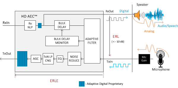
The top half of the diagram shows the receive signal path, or the signal path from the telephone network to the speaker. The bottom half of the diagram shows the transmit signal path from the microphone toward the telephone network. The HD AEC cancels the echo that occurs between the speaker output and the microphone input.
The terms Rx (Receive) and Tx (Transmit) may be confusing at first because both the receive and transmit paths have inputs and outputs. The names receive and transmit are used from the point-of-view of the person at the speaker/microphone side.
The RxIn signal coming from the network is fed into the RxNLP (Receive Nonlinear Processor). Under difficult acoustic conditions, the RxNLP can improve full-duplex operation and hence the overall voice quality.
The output of the RxNLP is fed both to the transmit output (TxOut) and into the bulk delay block. The bulk delay block compensates for the buffering delay at the RxOut and TxIn interfaces as well as any other non-acoustic system delays in the path between RxOut and TxIn. The output of the bulk delay is fed to the adaptive filter.
The adaptive filter estimates the echo and subtracts it from the TxIn signal to form the residual signal.
The residual signal is fed to the noise reduction block. This noise reduction block removes background noise and therefore improves the signal to noise ratio of the transmit signal.
The adaptive filter works in conjunction with the bulk delay monitor, which monitors and adjusts bulk delay in situations where the bulk delay is unknown due non-deterministic audio drivers.
The output of the noise reduction block is fed into an equalizer. The equalizer is used to flatten out the frequency response of the transmit channel. This may be necessary due to the acoustics of the hands-free device and due to the characteristics of the microphone itself.
The output of the transmit equalizer is fed into the transmit non-linear processor (TxNLP). The TxNLP increases the echo attenuation by attenuating the residual by a variable amount based upon the talk state. The TxNLP block also includes a comfort noise generator.
Automatic Gain Control (AGC) is provided to help boost lower level speech signals in hands-free environments. The compute gain block computes the AGC gain. The output of the TxNLP is fed into the AGC gain block, which provides gain or loss depending upon the residual signal level. The output of the AGC is fed to the TxOut output of the AEC.
In the multi-microphone case, there is still a single receive path but there is one transmit path per microphone.
In the case of multi-microphone noise reduction, there is a single receive path, a complete transmit path for the primary microphone, and a partial transmit path for the secondary microphone. In this case, there are two transmit inputs (one for each microphone) but only one transmit output containing the echo cancelled and noise reduced signal.
API Functions
API function call summary
HDAEC_
AEC_ADT_create(..) Create and initializes an echo canceller
AEC_ADT_createMMIC(…) – channel (single mic, multi-mic, dual-mic with noise reduction)
AEC_ADT_createDMNR(…)
AEC_ADT_apply(…) Executes cancellation function
AEC_ADT_applyMMIC(…)
AEC_ADT_applyTx(…) Executes Transmit Only (for applications that require split tx/rx processing
AEC_ADT_applyRx(…) Executes Receive Only (for applications that require split tx/rx processing
AEC_ADT_control(…) Modify AEC parameters. Obtain status.
AEC_ADT_controlMMIC(…)
AEC_ADT_delete(…) Deletes an echo canceller channel
AEC_ADT_deleteMMIC(…)
Significant Upgrades
"We have made significant changes to our core algorithm in order to boost efficiency. HD AEC operate in a higher audio bandwidth. We have improved implementation by simplifying and providing straight forward API."
Enhancements
Bi-directional NLP: Handles unbalanced speech levels of more than 18dB apart.
Achieves full-duplex performance even in close mic to speaker proximity: Automatic gain and level controls adjust levels automatically.
High Echo Return Loss (ERL) ratio: Ability to handle long tail lengths, speaker to microphone loss/gain, and feedback.
Enhanced double-talk detection /double-talk handling.
Fast reconvergence: Ability to adjust for echo path changes which can occur when someone moves inside the room, passes an object across the table, or enters or exits the room.
Demos
HD AEC: Get the demos
Demo request form will put you in contact with our sales team. They will supply you with a complete list of hardware requirements. Demo/Eval agreement will be required to download the software. Thank you for your interest!
HD AEC NXP MIMXRT685-EVK Arm® Cortex®-M33
Hardware Requirements: i.MX RT600 EVK (MIMXRT685-EVK)
HD AEC STM32F76xx Arm® 32-bit Cortex®-M7
HD AEC Full Duplex STM32F4 Demo Arm® 32-bit Cortex®-M4
Hardware Requirements: STM32F407G-DISC1, combined with the STM32F4BIS-BB extension board
HD AEC Linux VoIP Engine BeagleBone Green Demo
Hardware Requirements: BeagleBone Green (BBG), or BeagleBone Green Wireless (BBGW)