Understanding the Echo "Phenomenon" Causes and Solutions

The overall importance of echo cancellation should also not be overlooked.
From the users perspective, echo is arguably the worst type of impairment that can be encountered during a telephone conversation.
IMPORTANCE OF ECHO CANCELLATION
If you’ve ever spoken into an electronic communication device be it desk top, mobile, or hands free, you’ve undoubtedly experienced acoustic echo — you hear your own voice coming back to you through the device, sometimes with significant delay. The problem can range from simply annoying to absolutely unbearable. That’s why controlling echo is such a major consideration in telecom applications.
WHAT IS ECHO?
Sound is a waveform made from vibrating matter. Echo is defined as the repetition of a waveform. Echo in the context of telecom applications is the reflected sound of your own voice reverberating in the telephone receiver while you are talking. If the echo’s amplitude is low, it goes unnoticed, and is not problematic in the conversation; however, if the echo interval exceeds approximately 25 milliseconds (ms), it becomes audible to the speaker. Echo can be extremely disruptive to a conversation. It can so critically impair voice quality that it makes phones calls very unpleasant and distracting; very often to the point of non-comprehension of the conversation. Most echo laden telecom transactions are quickly abandoned by the participants.
ECHO IN TELECOMMUNICATION SYSTEMS
OVERVIEW
Echo is the sound of your own voice reverberating in the telephone receiver while you are talking. If the echo’s amplitude is low, it goes unnoticed, and is not problematic in the conversation; however, if the echo interval exceeds approximately 25 milliseconds (ms), it becomes audible to the speaker. Echo can be extremely disruptive to a conversation. It can so critically impair voice quality that it makes phones calls very unpleasant and distracting; very often to the point of non-comprehension of the conversation. Most echo laden telecom transactions are quickly abandoned by the participants.
ECHO TYPES
Acoustic
Audio loop back that occurs when a microphone(s), pick up audio signals from a speaker(s), and sends it back to an originating participant.
Line / Hybrid
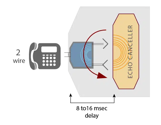
Mismatches within the hybrid where 4-wire phone circuits are converted to 2-wire circuits. Tail lengths of up to 16 msec are referred to as Short Tail (Line).
Network / Packet
Packet loss and Latency compound the undesirable effects of an echo. The longer the round-trip delay the more noticeable and disruptive the echo becomes.
ACOUSTIC ECHO
Acoustic echo originates in a local audio loop back that occurs when a microphone(s), pick up audio signals from a speaker(s), and sends it back to an originating participant. The originating participant will then hear the echo of the participant’s own voice as the participant speaks. Acoustic echo can be intensified when sensitive microphone(s) are used, as well as when the microphone and/or speaker volume is turned up to a high level, and also when the microphone and speaker(s) are positioned so that the microphone is close to one or more of the speakers. This echo is aggravated by reflective acoustic echo reflected by walls and/or objects.

Acoustic echo is a common problem with audio conferencing systems. It originates in the local audio loop-back that occurs when your microphone picks up audio signals from your the speaker, and sends it back to the other participant along with your voice. The other participant hears this echo of his or her own voice as he or she speaks.
Acoustic echo can be caused or exacerbated when very sensitive microphones are used, speaker volume is turned up very high, or the microphone and speaker are very close to one another. Besides being annoying, this can prevent normal conversation among participants in a conference.
SOLUTION
Acoustic Echo Cancellation (AEC ) is used to cancel acoustic feedback between a speaker and a microphone in loud-speaking audio systems, teleconferencing devices, hands free mobile devices, and voice-controlled systems.
Adaptive Digital’s high definition acoustic echo canceller (HD AEC™) is exceptional at handling echo. HD AEC has, has integrated both Noise Reduction, and Automatic Gain Control (AGC) into its AEC algorithm.
Adaptive Digital’s HD AEC software product provides superior voice clarity and true full duplex performance enabling simultaneous communication with no delay under a wide range of acoustic environments for both outdoor and indoor applications.
Adaptive Digital uses a proprietary fast converging adaptive filter, and non-linear processor to deliver robust double talk performance both indoors and even in unpredictable outdoor conditions.
The HD AEC algorithm eliminates acoustic echo in difficult conditions such as unbalanced speech levels, close speaker to mic proximity, background noise, wind noise, double talk, and echo path changes.
Adaptive Digital’s HD AEC acoustic echo cancellation technology can be found in a wide range of applications, like IP Intercom Systems, Conference Speakerphones for both large and small conference rooms/huddle rooms, IP Desk Phones, Mobile Handsets, Radio over IP, and essentially anywhere where voice quality is affected by adverse room conditions. Additionally, the HD AEC acoustic echo canceller is effective in improving the performance of speech recognition algorithms when operating in an echoic environments.
LINE ECHO
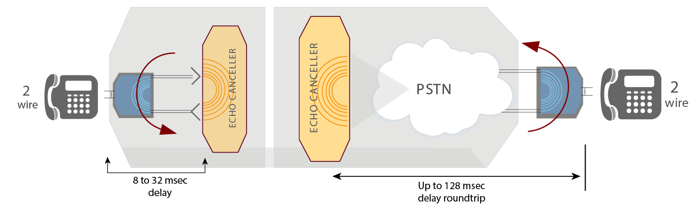
Line Echo occurs inside a device that has a local hybrid circuit. The hybrid circuit is the circuit that converts between a4-wire and a 2-wire interface. Hybrid is the most prevalent cause of echo in PSTN is impedance1 mismatches within the hybrid where 4-wire phone circuits are converted to 2-wire circuits. This electrically generated echo occurs when the incoming energy from the far end speaker is reflected back toward the speaker as a slightly altered and delayed replication due to impedance mismatch in the hybrid (Figure 1).
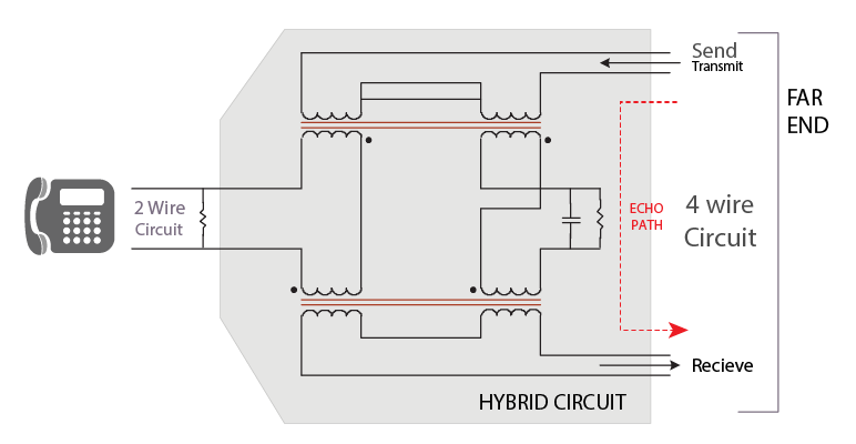
HYBRID
The presence of echo occurs whenever the replicated signal delay exceeds 10 msecs, and becomes apparent to the speaker as reflected voice when the delay exceeds as little as 16 msec. It is manifested to the far end as an altered replica of the speaker original.
Active hybrid circuits provide some echo reduction, but not enough when the end-to-end circuit delay is even moderate. The signal being reflected back is measured as ERL (Echo Return Loss), the higher the ERL, the lower the reflected signal back to the speaker.
Active hybrid circuits provide some echo reduction, but not enough when the end-to-end circuit delay is even moderate. The signal being reflected back is measured as ERL (Echo Return Loss), the higher the ERL, the lower the reflected signal back to the speaker. 1. Impedance: the apparent opposition in an electrical circuit to the flow of an alternating current that is analogous to the actual electrical resistance to a direct current and that is the ratio of effective electromotive force to the effective current.
Another type of echo, acoustic echo, is the undesired voiceband energy transfer from the speaker to microphone in a hands free telephone set or speakerphone.
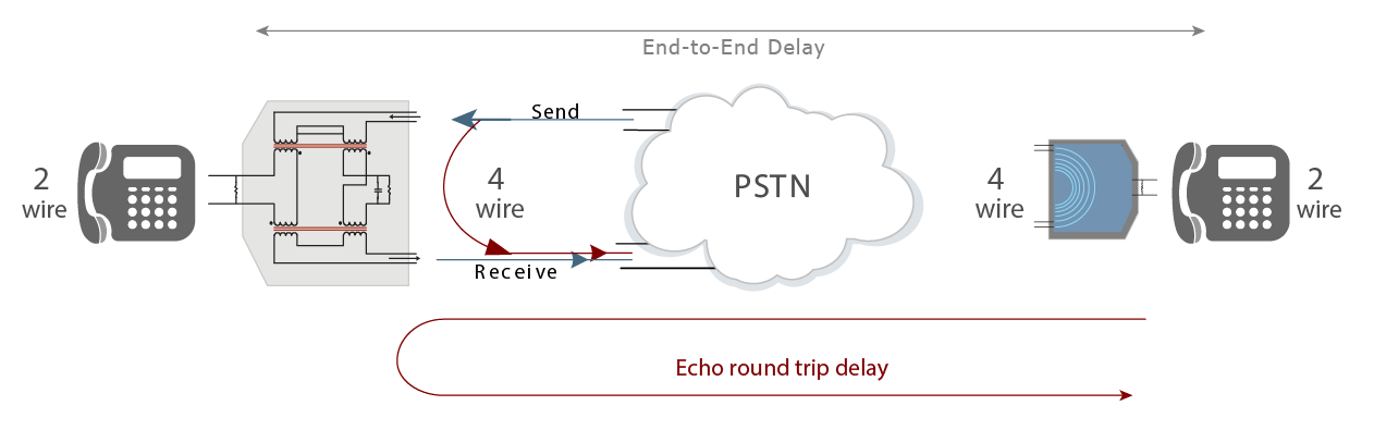
Delay in telephony context is the time during which voice signals travel across the network. End-to-end delay is the sum of delays required for a voice signal generated by the speaker’s mouth to cross the different network devices and network links in order to reach the listener’s ear. Round trip delay (Fig 2) is the sum of end-to-end delay in both directions as it is reflected back to the speaker’s ear. The two directions can take separate paths, one through a satellite and one via land-lines, for example.
HYBRID
Round trip delay
It is during round trip delay that echo becomes perceptible. The greater the round trip delay and impedance mismatch, the worse the potential echo.
Telephone Circuit
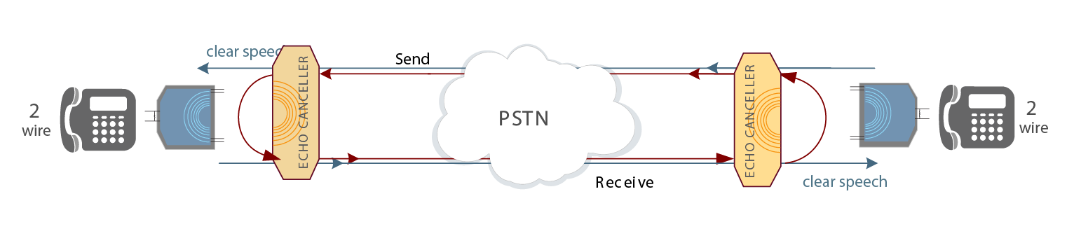
Phone A’s transmission passes through Hybrid A, through Echo Canceller A, through the Telephone Network, through Echo Canceller B, through Hybrid B to telephone B. A similar path is established in between Phone B and Phone A. When Phone A’s transmission reaches Hybrid B, part of the signal is reflected by the hybrid back towards Echo Canceller B and therefore back to Phone A.
ECHO TAIL
A hybrid circuit does not create a brick-wall echo. A brick wall echo refers to one where the response of a far end impulse would be an echoed impulse. Since the hybrid is a circuit, the impulse response of the echo path is of a diffuse nature. The impulse response of the hybrid circuit is referred to as the echo tail. The duration of the echo tail is referred as the tail length. An echo canceller must cancel the entire tail.
To make matters more interesting, it is possible that multiple echo sources can be present within the tail circuit. This situation is referred to as one with multiple echo tails. A good echo canceller will cancel echo due to all the echo sources in the network.
Tail lengths of up to 16 msec are referred to as Short Tail (Line). Tail lengths exceeding 16 msec, up to 128 msec are considered Long Tail (Network). Echo tail 128 to 512 msec arehandled with the G.168Plus Packet echo cancellation algorithm.
NEAR END / FAR END
The terminology Near End and Far End are usually used when referring to an echo canceller. For example, the Far End signal enters echo canceller A and passes through unchanged and is sent out to the hybrid. The hybrid, which is at the Near End with respect to echo canceller A, reflects a portion of the far end signal back towards the echo canceller. The Near End signal received by echo canceller A therefore consists of the sum of Phone A’s transmit signal and the echo of the far end induced by Hybrid A.
If echo cancellation is not performed (and the network delay is moderate), the speaker at Phone A will perceive his echo. It is the responsibility of Echo Canceller B to cancel the echo that is induced by Hybrid B. Likewise, it is the responsibility of Echo Canceller A to cancel the echo that is induced by Hybrid A.
ADAPTIVE FILTERING
As each hybrid circuit is slightly different, each echo tail is different as well. Many factors determine the echo path. It is even possible for an echo tail to change while a circuit is active. This could happen when a second telephone extension is taken off-hook in parallel with the first one. Due to these variations in echo tails, it is necessary for an echo canceller to adapt to the tail continuously. Adaptive Filtering is employed within echo cancellers to this end. The adaptive filters should converge quickly, but not so quickly that they might diverge under some conditions.
This is especially important when a circuit is first established. The amount of time it takes the echo canceller to adapt to an echo path is referred to as the “convergence time”.
ECHO: CONTRIBUTING FACTORS
The PSTN telephony network “cloud” itself is a source of delay, as are many points along the voice network: examples:
Compression delay:
- G.723.1: 37 msec
- G.729: 15 msec
- G.728: 2.5 msec
- Inter-process hand-offs: approx. 10 msec at each end
- Transmission lines: typically 1 msec per 100 miles of cable
- Satellite links: 250 to 270 msec, multiple hops can yield even longer delays
- Serial delay*: from 0.5 msecs for a 128K packet on a 2Mbps line, to 128.6 msecs
- For a 1024K packet on a 64Kbps line
- VoIP gateway node: 50 to 100 msec
- Decompression delay: typically 10 msecs or less
A point to remember is that any end-to-end phone connection can pass through many of the above components several times along the way. Delays introduced in voice traffic path are most pronounced in long distance and wireless telephone calls.
*Serial Delay: the amount of time taken to put a packet on a transmission line. This is dependent on packet size and line speed.
VOIP NETWORK COMPLICATIONS
LATENCY
Round-trip Latency, caused by the travel time necessary for a voice packet to reach its destination (where the echo is introduced as a reflection) and then return back to the speaker — who can now hear his own voice in the reflection, can significantly compound the undesirable effects of an echo. The longer the round-trip delay (and subsequently, the time between the original speech and its echo) is, the more noticeable and disruptive the echo becomes to a speaker. In fact, the added, network-induced, delay can make what is considered a negligible echo within traditional circuit switched networks, distracting enough to cause users to hang up and end the call. For two party calls the solution is to end the call and try again. In the case of a VoIP conference call where echo on one line negatively affects the quality heard by all listeners, the effect is multiplied and decidedly difficult to eliminate since any one (or more) of the listener’s circuits may be the source of the reflection. When a large number of callers participate in a conference call the probability that one or more of the lines have an echo problem increases exponentially with each added caller. Once identified, that person(s) must then hang up and dial back in, hopefully this time on an echo-free circuit. With the added delays introduced by IP network latencies, echo becomes more perceptible, and more problematic, to the caller.
Although it is the responsibility of the equipment causing the reflection to cancel the echo and prevent it from making its way back to the original speaker, telephone networks exist today that simply ignore this responsibility.
PACKET LOSS
Packet loss (one or more packets of data failing to reach its destination) can be extremely detrimental to echo cancellers that are unaware of the data loss. If the echo canceller is unaware of the momentary data interruption, it will process the synthesized data that fills in for the lost signal as if the echo were present. This can prevent the echo canceller from being able to detect and cancel the echo. Even worse, the lost data can cause the echo canceller to incorrectly determine the characteristics of the echo and, in its attempt to remove echo that isn’t truly an echo, render the speech intelligible.
The added delay incurred by the packet network can cause echo that is not otherwise perceptible to become a problem. This may include not only echo due to hybrid circuits but also some residual acoustic echo from handsets or hands-free devices. As a result, there could be equipment in the field that did not require echo cancellation before VoIP entered the picture.
Since it is not feasible to modify all such equipment, it is sometimes necessary for an echo canceller in a packet network to cancel echo whose source is on the opposite end of the packet network. A packet network echo canceller must be able to handle excessively long echo delays. It must also be able to operate well whether there is echo or not. In fact, it is far more common that a connection be echo free because the echo is cancelled at the source. Furthermore, a packet echo canceller must be able to deal with the presence of speech compression algorithms within the VoIP network.
Examples of equipment that may need a packet echo canceller include:
- VoIP Gateway
- VoIP Conference Serv
Adaptive Digital’s G.168+product provides a truly unique solution to what would otherwise be a lost call.
ECHO CANCELLATION PRODUCTS
G.168 ECHO CANCELLATION (non-acoustic)
Adaptive Digital’s voice quality enhancement algorithms are well suited to address all of the environmental issues required. In this instance, the acoustic noise reduction algorithm is particularly valuable in the presence of high level of background noise present.
Since the ability to provide voice quality of the highest standard depends mainly on selecting the right echo cancellation technology, Adaptive Digital’s highly regarded “carrier-class” G.168 patented echo canceller provides: rapid convergence, advanced comfort noise, and handles a 128 ms echo tail without a performance penalty. The G.168Plus Packet EC handles extraordinary round-trip delays of up to 512 milliseconds. Above all Adaptive Digital’s G.168 product and all it’s variants have a proven track record for providing excellent voice quality.

G.168 ECHO CANCELLER
The Adaptive Digital patented, industry standard, G.168 echo canceller is available on many DSP and general purpose processors.
Adaptive Digital’s echo canceller qualified as toll-quality at AT&T’s Voice Quality Assessment Labs in Middleton, NJ. AT&T’s Voice Quality Assessment Lab evaluated Adaptive Digital’s echo canceller using its stringent series of performance tests including AT&T’s Mean Opinion Score (MOS) subjective tests as well as the standardized set of G.168 objective tests. The subjective and objective performance of Adaptive Digital’s echo canceller surpassed even the performance of AT&T’s benchmark lab echo cancellers.
ADAPTIVE DIGITAL'S ECHO CANCELLATION SOLUTIONS
Line, Network, Packet, & Acoustic
G.168 Echo Cancellation: Line & Network
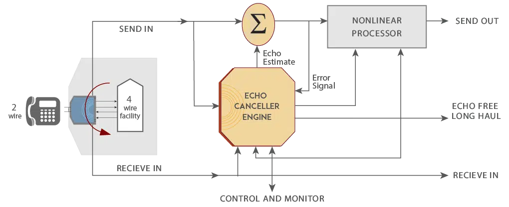
In order to combat the echo phenomenon, an echo canceller is employed. Today’s echo cancellers use sophisticated algorithms running on high speed Digital Signal Processors (DSPs) to combat the echo. By sampling the voice signal, the echo canceller can create a model of the echo path which is in turn used to estimate the echo. This estimation is then subtracted from the incoming voice signal allowing normal speech to pass through. This is a very simplistic view, as echo cancellers need to have the capability to sample multiple echoes occurring at different times and at different levels.
G.168 Echo Cancellation: Packet
G.168™Plus Packet , with its capability to cancel echoes with long delays, allows equipment manufacturers to give their customers superior voice quality on all calls by canceling echoes produced at other sites. G.168™Plus Packet has the unique ability to handle Tail lengths of 256, 384, & 512 msec.
High Definition Acoustic Echo Canceller (HD AEC)
Adaptive Digital’s HD AEC™ is a High Definition (HD), Full band (super wide to narrow), Multi-Mic Capable, Full-Duplex Acoustic Echo Canceller (AEC) which includes noise reduction (NR), as well as anti-howling, adaptive filtering, nonlinear processing, and double-talk detection.
HD AEC is capable of eliminating the acoustic echo in difficult conditions such as unbalanced speech levels, close speaker to mic proximity, background noise, indoor/outdoor environments, reflective room surface, double talk, and echo path changes.
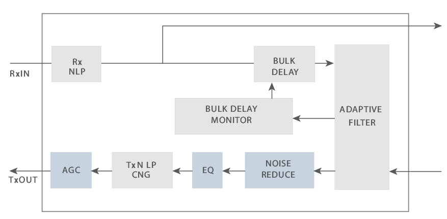
The above figure is a simplified block diagram of the HD Acoustic Echo Canceller.
The top half of the diagram shows the receive signal path, or the signal path from the telephone network to the speaker. The bottom half of the diagram shows the transmit signal path from the microphone toward the telephone network. The HD AEC cancels the echo that occurs between the speaker output and the microphone input.