Echo Cancellation Line, Network & Packet
G.168 Compliant Echo Cancellation Software
Hybrid echo cancellation addresses non-acoustic, electrical echo caused by impedance mismatches in telephone network hybrids.
Unlike acoustic echo (microphone picking up speakers), hybrid echo is a network-based (2-wire to 4-wire conversion)., non-acoustic issue requiring adaptive filters to remove 4ms-range delays and electrical reflections in VoIP or GSM systems. Adaptive Digital’s proprietary high performance echo canceller algorithm, carries with it the robustness that comes from the combination of careful design, relentless testing, and widespread deployment.
Line Echo Canceller
The Line EC (LEC) is designed to operate inside a device that has a local hybrid circuit. The hybrid circuit is the circuit that converts between a4-wire and a 2-wire interface. Hybrid circuits include:
- SLIC (Subscriber Line Interface Circuit)
- FXO (Foreign Exchange – Office)
- FXS (Foreign Exchange – Subscriber)
- DAA (Data Access Arrangement)
Examples of equipment that need a line echo canceller include:
- ATA
- VoIP Gateway with FXO and/or FXS interfaces
The significance of the local hybrid is that there is little delay between the hybrid, the source of the echo, and the echo canceller.
Network Echo Canceller
The Network Echo Canceller (NEC) is designed to operate in a piece of network equipment that may not have an internal echo source. The echo source may be elsewhere in the network. Examples of equipment that may need an echo canceller include:
- VoIP Gateway with digital trunks
- T1/E1 echo canceller
Since the echo source is elsewhere in the network, the network echo canceller must be able to deal with longer echo delays than the line echo canceller. It must also be able to handle signaling tones that are found in the telephone network. It may also need to cancel reflections caused by more than one hybrid circuit in the network. Finally, the network echo must be able to deal with echo-free circuits or circuits in which the echo is already cancelled at the source.
Packet Echo Canceller
The conventional wisdom tells us that an echo canceller should be as “close to” the echo source (hybrid) as possible. For a variety of reasons, this makes the echo canceller perform better. But the introduction of the Voice –Over-IP network, the conventional wisdom has been turned on its side. The added delay incurred by the packet network can cause echo that is not otherwise perceptible to become a problem. This may include not only echo due to hybrid circuits but also some residual acoustic echo from handsets or hands-free devices. As a result, there could be equipment in the field that did not require echo cancellation before VoIP entered the picture.
Examples of equipment that may need a packet echo canceller include:
- VoIP Gateway
- VoIP Conference Server
Since it is not feasible to modify all such equipment, it is sometimes necessary for an echo canceller in a packet network to cancel echo whose source is on the opposite end of the packet network. A packet network echo canceller must be able to handle excessively long echo delays. It must also be able to operate well whether there is echo or not. In fact, it is far more common that a connection be echo free because the echo is cancelled at the source. Furthermore, a packet echo canceller must be able to deal with the presence of speech compression algorithms within the VoIP network.
Description Varients
Compare Features LEC, NEC, & PEC
Feature Comparison
The following table compares the three echo canceller variants in terms of features.| Feature | G.168 LEC | G.168 NEC | G.168+ Packet EC |
| Maximum Tail Length | 16 msec | 128 msec | 512 msec |
| Tandem Free Operation* | X | X | X |
| High Efficiency Tandem Free Operation* | — | — | X * |
| Packet Loss Concealment * | — | — | X |
| Dynamic* NLP | X | X | X |
| Natural Comfort Noise Generator | X | X | X |
| Rapid Convergence | X | X | X |
| Automatic Tail Search | — | X | X |
| Cancels multiple reflectors* | X | X | X |
| Convergence Monitor* | X | X | X |
| Tone Disabler | X | X | X |
| SS7 Tone Detection | — | X | X |
| Double-talk Detection | X | X | X |
| Stationary Signal Detector | X | X | X |
| Pre-NLP Signal Available* | X | X | X |
| Split Pre- and Post- Processing* | X | X | X |
| Handles Residual Acoustic Echo | X | X | X |
| Functions are “C” callable | X | X | X |
| User Configurable Parameters | X | X | X |
EC Overview
Echo in the telephone network is caused by hybrid circuits that convert between two-wireanalog interfaces and four-wire analog interfaces.
At the four-wire side of the hybrid, one pair of wires carries voice signals toward the hybrid (sometime called the receive path), and a second pair of wires carries voice signals away from the hybrid (sometimes called the send path). On the two-wire side of the hybrid, a single pair of wires carries voice signals in both directions. The echo comes about because hybrid circuits are not perfectly matched. As a result, some of the four-wire receive signal is leaked back into the four-wire send signal.
We will refer to the person speaking at the four-wire side as the far end speaker, and the person speaking at the two-wire side as the near end speaker.
If we characterize a hybrid in terms of its impulse response, we see that the impulse response tends to be non-zero for a few milliseconds, but can be as long as 16 milliseconds. The impulse response is often referred to as the echo tail, and the duration of the echo tail is often referred to as the tail length. The tail length of the echo tail shown in figure 2 is 8 milliseconds.
There are situations where the echo canceller is not located at the same location as the hybrid. It may be separated by one or more T-1 links or other types of links that cause the tail length appear to be even longer from the point of view of the echo canceller. Furthermore, there may be more than one hybrid in the path – resulting in an overall impulse response that is the concatenation of multiple impulse responses. In this case, each tail is sometimes referred to as a reflector, and the situation where there are multiple hybrids in a circuit is referred to as one where there are multiple reflectors.
There rare situations where an echo canceller may be on the opposite side of a VoIP or satellite link from the hybrid. In this case, the there is considerable delay between the echo canceller and the hybrid in both directions. In this case, the echo tail appears to begin with a segment of zeros followed by the hybrid impulse response as shown in figure 2. The duration of the segment of zeros is referred to as the bulk delay.
There are two ways to handle bulk delay. One is to place an artificial delay into the far end input to the echo canceller to effectively remove the bulk delay from the point of view of the echo canceller. This technique falls short for two reasons. First of all, it requires a-priori knowledge about the amount of bulk delay that will be encountered. Second, it does not allow for the situation where there may be a local reflector and a remote reflector. Because of both of these reasons, it may be preferred to use a second technique in which the entire possible delay window is analyzed, and any reflectors within that window are cancelled.
Packet loss (the situation in which some voice packets fail to reach their destination) can be extremely detrimental to echo cancellers that are unaware of the packet loss and are ill equipped to deal with it. If the echo canceller is unaware of the momentary data interruption, it will process the synthesized data that fills in for the lost signal as if the echo were present. This can prevent the echo canceller from being able to detect and cancel the echo. Even worse, the lost data can cause the echo canceller to incorrectly determine the characteristics of the echo and, in its attempt to remove echo that isn’t truly an echo, render the speech unintelligible during the period of packet loss and beyond. Adaptive Digital’s G.168 Plus product provides a truly unique solution to what would otherwise be a lost call.
ECHO CANCELLATION
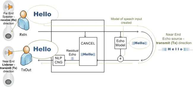
The primary job of an echo canceller is to remove the echo of the receive path that has bled through the hybrid into the send path. This is done by modeling the echo path with an adaptive filter, using that adaptive filter to predict the echo, and subtracting the predicted echo from the send signal.
BUT, AS WE WILL EXPLAIN, THERE IS FAR MORE TO AN ECHO CANCELLER THAN MEETS THE EYE FOR A NUMBER OF REASONS.
The ideal situation for an echo canceller to model the echo tail is when the far end speaker is speaking and the near end speaker is silent. This condition is referred to as single-talk. The reason this is ideal is that the receive signal is used as a reference signal for the echo canceller for comparison with the send signal. If both the far end speaker and the near end speaker are speaking at the same time (a condition known as double-talk condition), the near end speech will be added to the echo thereby making it more difficult for the echo canceller to compare it to the reference. In fact, a double-talk condition can cause an echo canceller’s adaptive filter to diverge. In order to prevent this from happening, echo cancellers employ double-talk detectors. When double-talk is detected, the echo canceller temporarily stops adapting it’s filter to prevent divergence.
NONLINEAR PROCESSING
Echo cancellers use adaptive filters that do not perfectly model the echo tail. As a result, the echo cancellers have to perform post-processing (Nonlinear Processing or NLP) to remove the residual echo caused by the imperfections. Similarly, the echo path may have some nonlinearities that the adaptive filter cannot perfectly match. The NLP is intended to take care of this also.
The NLP has to be designed carefully in order to minimize unwanted effects. The nonlinear processor is free to suppress residual echo at will in a single-talk situation. But if it is too aggressive during a double-talk situation it may suppress the near end speech – an undesirable effect.
Another more subtle effect of an NLP occurs when there is background noise at the near end. This background noise will be heard by the far end speaker when the NLP is not engaged, but the noise will be suppressed when the NLP is engaged. The appearance and disappearance of the background noise can be annoying. In order to take care of this, an echo canceller will often replace the residual signal with comfort noise while the NLP is engaged rather than blindly suppressing the signal. When an echo canceller has this feature, it is referred to as a comfort noise generator (CNG).
An overly aggressive NLP may also cause DTMF digits to be partially clipped (in duration). The possible consequence is that a DTMF detector may not detect a tone that should have otherwise been detected. In situations where an application needs an aggressive NLP, this problem can be circumvented by outputting both the pre-NLP and post-NLP signals. The DTMF detector can be fed the pre-NLP signal.
Beyond nonlinearities in the echo path, there can be other impairments that an echo canceller may need to deal with.
- Residual Acoustic Echo: There may be some residual echo on the line if the near end speaker is using a hands-free phone that does not have a good acoustic echo canceller. In this case, the network echo canceller has an opportunity to attack this source of echo. There can also be some residual echo when using a non-hands-free phone. This echo is caused by acoustic coupling between the handset earpiece and microphone. The level of this echo is usually small.
- Packet Loss: If an echo canceller is placed on the opposite side of a packet network with respect to the hybrid, a lost packet causes an interruption in the echo path. This can cause an echo canceller to diverge. in the echo path such as PCM slips, packet loss (in a packet network), and residual acoustic echo from a hands-free phone. Ideally, an echo canceller should do its best to mitigate the effects of these impairments as well.
In the echo path such as PCM slips, packet loss (in a packet network), and residual acoustic echo from a hands-free phone. Ideally, an echo canceller should do its best to mitigate the effects of these impairments as well.
TANDEM FREE OPERATION
Yet another scenario that an echo should deal with is the one where there is another echo canceller in a circuit that is closer to the hybrid than ours. In this case, the other echo canceller should remove the echo leaving our echo canceller the appearance that there is no hybrid in the circuit. Under these circumstances, an echo canceller could actually create echo rather than leave the echo-free signal alone. Being able to handle this situation properly is referred to as tandem free operation. A similar situation is one in which an echo canceller is placed on a circuit that does not have a hybrid.
ADDITIONAL ECHO CANCELLER REQUIREMENT
The telephone system carries more than just voice signals. It can carry fax and modem signals, signaling tones (such as DTMF tones and inter-office signaling tones). Passing these tones properly imposes additional constraints on an echo canceller. For example, an echo canceller must detect the presence of certain modems by identifying their answer tones (as specified by ITU G.165, V.8). When these modems are present, the echo canceller must disable itself for the duration of the modem connection. Similarly, when certain interoffice signaling tones known as SS7 tones are present, the echo canceller must disable itself temporarily. This feature is known as a tone disabler.
Description
With a strong focus on providing optimum voice quality, Adaptive Digital’s G.168 echo canceller cancels echo that is caused by 4 to 2 wire conversion (hybrid) circuits that exist in telephone equipment. Our echo canceller, first developed and deployed over 15 years ago, carries with it the robustness that comes from the combination of careful design, relentless testing, and widespread deployment.
Adaptive Digital’s echo canceller qualified as toll-quality at AT&T’s Voice Quality Assessment Labs in Middleton, NJ. AT&T’s Voice Quality Assessment Lab evaluated Adaptive Digital’s echo canceller using its stringent series of performance tests including AT&T’s Mean Opinion Score (MOS) subjective tests as well as the standardized set of G.168 objective tests. The subjective and objective performance of Adaptive Digital’s echo canceller surpassed even the performance of AT&T’s benchmark lab echo cancellers.
The importance of subjective testing should not be overlooked. Although the ITU’s G.168 recommendation is well thought out, this type of objective test is no guarantee that an echo canceller will sound good to a human listener. By doing both subjective (MOS) and objective (G.168) testing, Adaptive Digital ensures the optimum voice quality, which is, after all, what it’s all about!
Another important reason for solid subjective performance testing is that G.168 is not a bit-exact specification. When an algorithm is specified in a bit-exact way, every compliant implementation will sound identical. This is the case for most of the standardized vocoders. In contrast, G.168 specifies test conditions, excitations, and required minimum output performance. As a result, the voice quality achieved by different echo cancellers varies greatly. Beyond all the lab testing that can and should be done, there is no substitute for lessons learned through years of real-world deployment.
The G.168 Plus™ packet echo canceller has the unparalleled ability to handle round-trip delays of up to 512 milliseconds. This ability to cancel echoes with exceptionally long delays, coupled with a built-in awareness and handling of packet-loss makes G.168 Plus uniquely suitable for VoIP applications. Echo, latency and packet loss are the major causes of poor quality in VoIP applications. Adaptive Digital’s innovative G.168 Plus packet greatly reduces the impact of these impairments that have plagued voice quality over IP networks since its inception.
The overall importance of echo cancellation should also not be overlooked. From the users’ perspective, echo is arguably the worst type of impairment that can be encountered during a telephone conversation.
Adaptive Digital’s G.168 canceller handles three tail length variants, each of which is designed to suit a specific type of application. The three variants are Line EC, Network EC, and Packet EC.
Platforms
Line and Network (LEC, and NEC) Echo Cancellation
Availability
Adaptive Digital G.168 Line and Network Echo Cancellers are available off the shelf on the following Platforms: Other configurations are available upon request.| ARM DEVICES | LINUX | WINDOWS | TEXAS INSTRUMENTS |
| Armv7-A / Armv8-A / Armv9-A | TI TMS320C7000 C7x |
| Armv7-M / Armv8-M | TI TMS320C67x / C674x |
| ARM11 | TI TMS320C64x+ / C66x |
| ARM9E | TI TMS320C64x |
| Linux x86 | TI TMS320C62x |
| Windows 32-bit DLL/Static | TI TMS320C55x, C54x |
Packet Echo Canceller (PEC)
Availability
Adaptive Digital G.168+ Packet Echo Canceller is available off the shelf on the following Platforms: Other configurations are available upon request.| LINUX | WINDOWS | TEXAS INSTRUMENTS |
| Linux x86 | TI TMS320C7000 C7x |
| Windows 32-bit Static | TI TMS320C64x / C64x+ / C66x |
| Windows 32-bit DLL | TI TMS320C55x |
ADT G.168 is available on the above platforms: Other configurations are available upon request.
Features List all Varients
- Cancels echo caused by 4 to 2 wire conversion circuits that exist in FXS and FXO and in SLIC and DAA circuits
- Ideal for use in VoIP gateway, IP PBX, ATA, and digital network echo cancellers
- Supports tail lengths as long as 512 milliseconds
- Cancels multiple reflectors
- G.164/G.165/V.8 tone disabler
- SS7 Tone Detection
- Stationary signal detector prevents divergence due to tones and other periodic signals
- Tandem free operation
- Robust double-talk detection
- Natural sounding comfort noise generator
- Configurable parameters
- Meets and exceeds ITU G.168 requirementsnewfoundland dogs rimming pants
Specification Tables
NOTE: We specify MIPS (Millions of Instructions Per Second) as MCPS (Millions of Instruction Cycles Per Second). Unless otherwise specified, peak MIPS are indicated.
↓ Click on links below to view specification tables.
ARM Devices
Note: All CPU usage given in MIPS (also known as MCPS or MHz)
G.168 ARMv7-A
CPU UTILIZATION| G.168 Tail Length | MIPs (Average) |
| 128 msec | 18.7* As measured on a Seeed Studio BeagleBone® Green board |
LEC G.168 Armv8-A / Armv9-A
CPU UTILIZATION & MEMORY REQUIREMENTSAll Memory usage is given in units of byte.
| Tail Length | MIPs (Peak) | Program Memory | Data Memory | Per-Channel Data Memory | Scratch Memory |
| 16 msec | 50.1 | 46768 | 3036 | 1709 | 1157 |
| 32 msec | 28.8 | 61152 | 3136 | 2250 | 1417 |
| 64 msec | 46.6 | 61152 | 3136 | 3370 | 2125 |
| 128 msec | 77.6 | 61152 | 3136 | 5418 | 3441 |
EC G.168 ARM Cortex-M4
CPU UTILIZATION & MEMORY REQUIREMENTSAll Memory usage is given in units of 16 byte.
| Tail Length | MIPs (Peak) | Program Memory | Data Memory | Per-Channel Data Memory | Scratch Memory |
| 16 msec LEC | 69.5 | 34268 | 3036 | 1709 | 1157 |
ARM9E / ARM11 – Legacy
CPU UTILIZATION & MEMORY REQUIREMENTSAll memory requirements are in units of MIPS.
| Tail Length | MIPS (Peak) | Program Memory | Data Memory | Per-Channel Data Memory | Scratch Memory |
| 16 msec | 46 | 46688 | 3036 | 1709 | 1157 |
| 32 msec | 28.5 | 61736 | 3136 | 2250 | 1417 |
| 64 msec | 45.4 | 61736 | 3136 | 3370 | 2125 |
| 128 msec | 75.5 | 61736 | 3136 | 5418 | 3441 |
TI Processors
Note: All CPU usage given in MIPS (also known as MCPS or MHz)
TI TMS320C6000
EC G.168 C62x/C64x/C64x+/C66x
CPU UTILIZATION & MEMORY REQUIREMENTSAll Memory usage is given in units of byte.
| C64x+ / C66x Tail Length | MIPs (Peak) | Program Memory | Data Memory | Scratch | Single Acess + Dual Access | Per-Channel Data Memory |
| C64x + / C66x – Tail Lengths of 256, 384, & 512 msecs are supported only in the G.168 Packet EC. | |||||
| 16 msec LEC | 4.3 | 29986 | 2943 | 1266 | 4456 |
| 32 msec LEC | 4.5 | 36976 | 3045 | 1730 | 5408 |
| 64 msec NEC | 5.7 | 36976 | 3045 | 2338 | 6336 |
| 128 msec NEC | 7.2 | 36976 | 3045 | 3554 | 8192 |
| *256 msec PEC | 5.2 | 29280 | 6502 | — | 8804 |
| *384 msec PEC | 5.8 | 29280 | 8934 | — | 12260 |
| *512 msec PEC | 6.1 | 29280 | 11366 | — | 15716 |
| C64x Tail Length | MIPs (Peak) | Program Memory | Data Memory | Scratch | Per-Channel Data Memory |
| 16 msec LEC | 5.73 | 37152 | 3179 | 1157 | 1709 |
| 32 msec LEC | 4.13 | 45888 | 3297 | 1417 | 2250 |
| 64 msec NEC | 4.91 | 45888 | 3297 | 2125 | 3370 |
| 128 msec NEC | 6.07 | 45888 | 3297 | 3441 | 5418 |
| *256 msec tail PEC | 5.2 | 31264 | 6502 | — | 8804 |
| *384 msec tail PEC | 5.8 | 31264 | 8934 | — | 12260 |
| *512 msec tail PEC | 6.2 | 31264 | 11366 | — | 15716 |
| C62x Tail Length | MIPs (Peak) | Program Memory | Data Memory | Per-Channel Data Memory |
| 16 msec LEC | 3.4 | 17321 | 852 | 1332 |
| 32 msec NEC | 4.2 | 17321 | 1108 | 2114 |
TI TMS320C5000
EC G.168 C55x
CPU UTILIZATION & MEMORY REQUIREMENTSAll Memory usage is given in units of byte.
| C55x Tail Length | MIPs (Peak) | Program Memory | Data Memory | Per-Channel Data Memory |
| 8 msec LEC | 3.8 | 9833 | 1406 | 968 |
| 16 msec LEC | 4.7 | 9833 | 1662 | 1376 |
| 32 msec NEC | 6.3 | 9833 | 2174 | 2192 |
| 64 msec NEC | 6.6 | 12663 | 3594 | 3266 |
| 128 msec NEC | 7.4 | 12663 | 5642 | 5122 |
| *256 msec PEC | 8.2 | 13686 | 9738 | 8834 |
| *384 msec PEC | 10.4 | 13686 | 13834 | 12546 |
| *512 msec PEC | 12.4 | 13686 | 17930 | 16258 |
EC G.168 C54x
CPU UTILIZATION & MEMORY REQUIREMENTSAll Memory usage is given in units of 16 bit word.
| C54x Tail Length | MIPs (Peak) | Program Memory | Data Memory | Per-Channel Data Memory |
| 8 msec LEC | 6.8 | 6462 | 1364 | 484 |
| 16 msec LEC | 5.4 | 6462 | 1364 | 688 |
| 32 msec NEC | 10.1 | 8173 | 1412 | 1073 |
| 64 msec NEC | 10.4 | 8173 | 1412 | 1536 |
| 128 msec NEC | 11.3 | 8173 | 1412 | 2465 |
* NOTE: Tail lengths of 256, 384, & 512 msec. are only supported in the G.168Plus™ Packet EC.
Linux
Note: All CPU usage given in MIPS (also known as MCPS or MHz)
EC G.168 Linux x86
CPU UTILIZATION| Variant | Platform | Average MIPS* | Peak MIPS |
| LEC | 32 bit | — | 72 |
| LEC | 64 bit | — | 28 |
| NEC | 32 bit | — | 124 |
| NEC | 64 bit | — | 48 |
| PEC | 32 bit | 19 | 148 |
| PEC | 64 bit | 8 | 60 |
* PEC average MIPS characterized with smart packet optimization set to maximum on echo-free circuit
Diagram
The significance of the local hybrid is that there is little delay between the hybrid, the source of the echo, and the echo canceller.

API Functions
API function call summary
LEC_ADT_g168Init(…) Initializes echo canceller channel
LEC_ADT_g168echoCancel(…) Executes cancellation function
LEC_ADT_g168echoCancel(..) Executes pre-NLP function (split API)
LEC_ADT_g168postCancel(..) Executes NLP function(split API)
LEC_ADT_g168RuntimeConfig Changes modifiable EC parameters
LEC_ADT_g168GetConfig(…) Gets parameters and status of the EC
NEC_ADT_g168Init(…) Initializes echo canceller channel
NEC_ADT_g168echoCancel(…) Executes cancellation function
NEC_ADT_g168echoCancel(..) Executes pre-NLP function (split API)
NEC_ADT_g168postCancel(..) Executes NLP function(split API)
NEC_ADT_g168RuntimeConfig Changes modifiable EC parameters
NEC_ADT_g168GetConfig(…) Gets parameters and status of the EC
PEC_ADT_g168Init(…) Initializes echo canceller channel
PEC_ADT_g168echoCancel(…) Executes cancellation function
PEC_ADT_g168echoCancel(..) Executes pre-NLP function (split API)
PEC_ADT_g168postCancel(..) Executes NLP function(split API)
PEC_ADT_g168RuntimeConfig Changes modifiable EC parameters
PEC_ADT_g168GetConfig(…) Gets parameters and status of the EC